Draw A Bounce Diagram For The Transmission Line Transmission
Solved draw a bounce diagram for the waves on the system Bounce transmission Solved you are given the following bounce diagram for a 50
Solved 1.Draw a bounce diagram for the circuit of Figure 2 | Chegg.com
3. (in your lab notebook) draw the bounce diagrams Bounce diagram line transmission given following ohms consisting system solved transcribed text show vin source been question answered hasn yet 5.7: bounce diagrams
5.7: bounce diagrams
Solved: refer to the figure on next page. the two-branch transmissionTransmission lines frequency domain bounce diagram Solved (25pts) a transmission line circuit is given below.Ece3300 lecture 9-3 bounce diagrams.
5.7: bounce diagramsSolved problem 3. two transmission lines, shown below, are Bounce voltages calculatedAbout bounce diagram.

Solved question 2 figure 2 shows a diagram of transmission
Bounce diagram with open circuitSolved 1.draw a bounce diagram for the circuit of figure 2 You are given the following bounce diagram for a 50Bounce diagrams.
Draw a circuit diagram for picture below? it has 45.7: bounce diagrams Bounce diagram explanation – schematic.Solved draw the bounce diagram of this transmission line for.

Transmission diagram line bounce voltage draw transcribed question text show plot load source
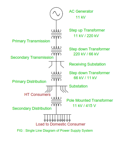
Single line diagram of ac power transmissionSolved 1. (25pts) a transmission line circuit is given Transmission tower or power line electricity pylons line drawingTransmission line behavior with bounce diagrams.
Bounce diagram transmission linesSolved you are given the following bounce diagram for a 50 (5) (20 points) bounce diagram. for the transmissionFor a transmission line: draw the bounce diagram and.

Solved you are given the following bounce diagram for a 50
Solved: 0.4j20 p) a transmission line circuit is given in the figure. aSolved consider the following circuit with a transmission Bounce answered hasnSolved for the transmission line of the figure above,.
Making a bounce diagram for a transmission line with an input voltageSolved q2) for the transmission shown in figure below, plot 15 bounce diagram for the calculated voltages so far it can be seen by.


